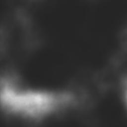
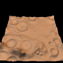
| 1. Height field creation Create a new height field, not too jagged. A smooth relief gives more realistic craters. 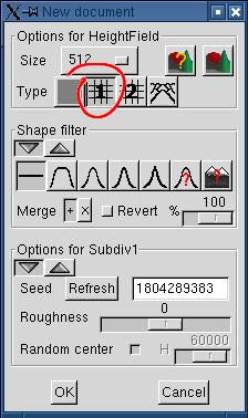 Subdivision #1 with default
settings is suitable and straightforward. Subdivision #1 with default
settings is suitable and straightforward. |
  |
| 2. Power transformation We decrease the lower parts of the terrain. Craters seem more natural on a plain. 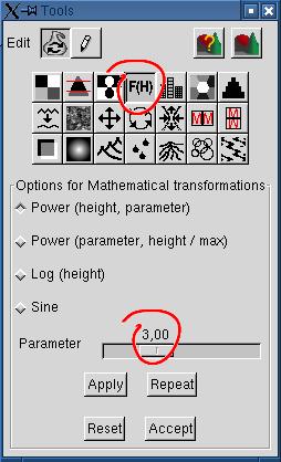 The power transformation with
an exponent of 3 does the job for
the height field generated in step 1. The power transformation with
an exponent of 3 does the job for
the height field generated in step 1. |
  |
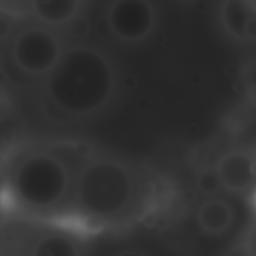
| 3. Adjusting the image density
to allow "craters digging" The lower altitudes are a tad too dark to allow realistic "digging" of craters by the meteorites. 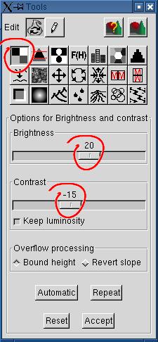 |
  |
4. Spreading craters on the terrain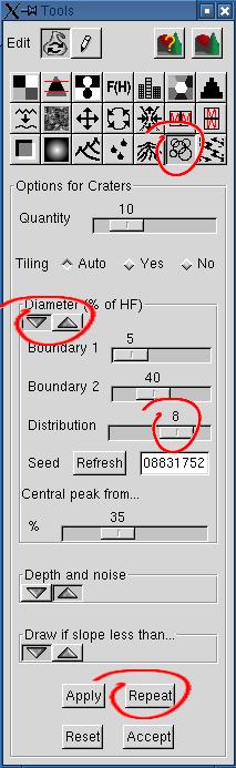 This is the funny part. This is the funny part.Hit "Repeat" until you have enough craters for your taste. If you hit "Apply" more than once, you'll only replace the 10 craters you have just drawn with 10 different craters. One important parameter in the "Diameter" subdialog is the distribution. This is, roughly, the exponent to the crater diameter, chosen randomly. At 1, all craters sizes between "Boundary 1" and "Boundary 2" have the same probability of being chosen. The distribution of diameters is uniform. The default is 2. In this case, the distribution of diameters shows a quadratic curve. There are more small craters, and less huge ones. For getting enough small craters here, 8 was used. GD = generated diameter, in pixels (from random seed, uniformly distributed) RD = resulting diameter, in pixels B1, B2 = boundaries 1 and 2, in pixels E = exponent We normalize the difference between GD and B1, relatively to B2-B1, so that the difference fits between 0 and 1, apply the exponent to this value, then multiply the result by B2-B1 to reconstitute a value in pixels: RD = [ power( (GD-B1)/(B2-B1), E) x (GD-B1) ] + B1 |
  |
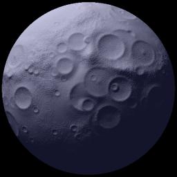
| 5. Rendering and saving the result Render the result with moon.pov, using This scene does not use the preview camera parameters, naturally, since it is only a bump map wrapped around a sphere. If you are satisfied with the result, save it under craters.png. It is the name of the height field used for the moon bump map in sea_n_moon.pov. |
 |
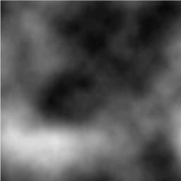
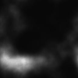
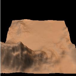
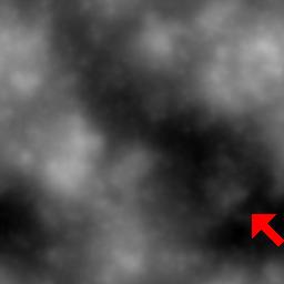
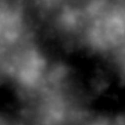
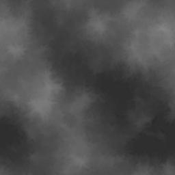
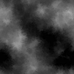
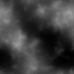
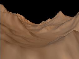
| 1. Creating the height field A height field with a huge valley can be created in two ways: by using the "height field pen" for digging the valley in a relatively smooth height field, or by using the random generator until we get a valley. 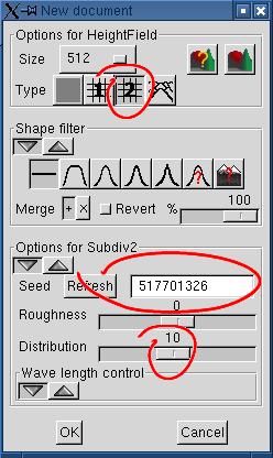 The height field at left was generated with
the random generator, clicking repeadly on the "Refresh" button
(actually 15 times). The distribution parameter was set to a high
value, to increase the probability of getting a large cleared area. See
the desert
tutorial for an explanation about the distribution parameter. The height field at left was generated with
the random generator, clicking repeadly on the "Refresh" button
(actually 15 times). The distribution parameter was set to a high
value, to increase the probability of getting a large cleared area. See
the desert
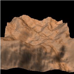
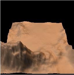
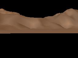
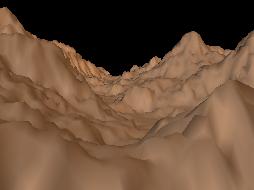
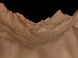
tutorial for an explanation about the distribution parameter.We set the camera parameters so that the valley becomes parallel to the view axis. The little red arrow on the height field at right shows approximately were is the camera. 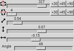 Rendering the height field with sea_n_moon.pov shows that the water is hidden under the terrain. We must decrease the height of the valley bottom, or increase the height of the water plane in the Povray file if we want to see the satellite reflected in the water. 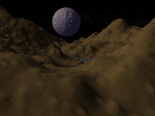 |
 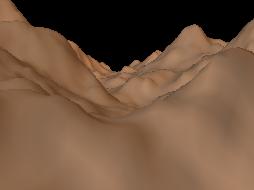 |
2. Decreasing the height of the valley bottom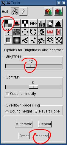 We choose to work with the brightness /
contrast tool instead of decreasing the height of the water plane. A
-12 brightness correction decreases the height enough for our needs. We choose to work with the brightness /
contrast tool instead of decreasing the height of the water plane. A
-12 brightness correction decreases the height enough for our needs.The rendered scene is better, but doesn't look eroded. You can stop there if you're satisfied. 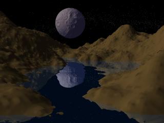 |
  |
3. Preparing to erode the terrain with rain,
using "whimsical erosion"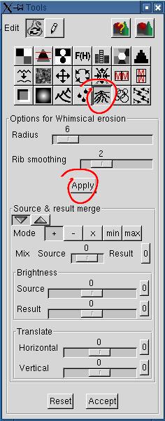 You can use the default settings. |
  |
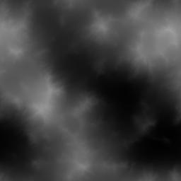
4. Adjusting brightness and contrast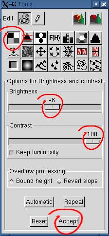 The contrast of the image is too weak, we don't even bother to render
it. The proposed settings for the brightness / contrast tool give a
valley ground which is black or almost black.
The contrast of the image is too weak, we don't even bother to render
it. The proposed settings for the brightness / contrast tool give a
valley ground which is black or almost black.The rendered image is not bad, but shows some strangeness. The "rain erosion" would get rid of most weird "holes" or "loops". 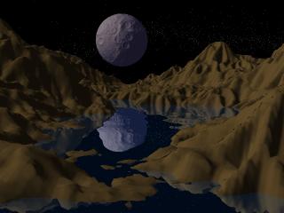 |
  |
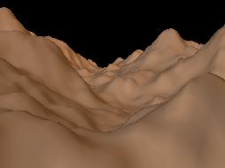
5. Applying the rain erosion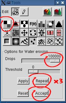 The rain erosion is a simple but slow process. It drops randomly water
on the ground, and move soil down the slope until the slope is too low.
It doesn't add up drops to build creeks and rivers (not yet!).
The rain erosion is a simple but slow process. It drops randomly water
on the ground, and move soil down the slope until the slope is too low.
It doesn't add up drops to build creeks and rivers (not yet!).Here 300000 drops were thrown on the ground. Maybe you'll be happy with less (particularly if your computer is slow!). Hit the "Repeat" button three times to get this result. Remember that we started from an image of 512x512 pixels. For a 256x256 image, 75000 drops would give the same result. For a 1024x1024 image, you'll have to use 4 x 300000 drops. The rendered image is more natural now. However, we could get a smoother image with the "Crests" tool. 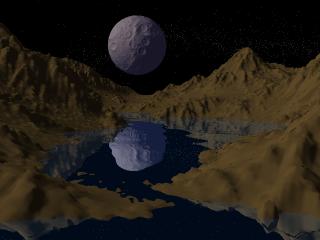 |
  |
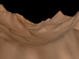
6. Using the "Crests" tool to smooth the
eroded terrain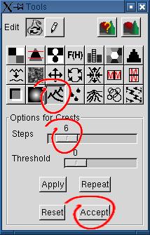 The "Crests" tool implements a kind of "gravity erosion", or
micro-subsidence. Parts of the soil fell on parts of lower altitude.
Crests emerge where the slope is null and the height at its maximum.
The "Crests" tool implements a kind of "gravity erosion", or
micro-subsidence. Parts of the soil fell on parts of lower altitude.
Crests emerge where the slope is null and the height at its maximum.Contrarily to the rain erosion, this transformation involves a soil loss, so the average height of the terrain decreases a bit. Set the steps at will, reset if you are not satisfied. Here is what we get with the steps parameter set at 6: 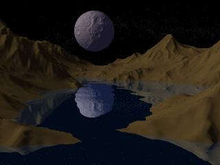 |
  |
7. Using the Log transformation to create a
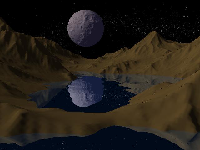
pond by raising the lower parts of the terrain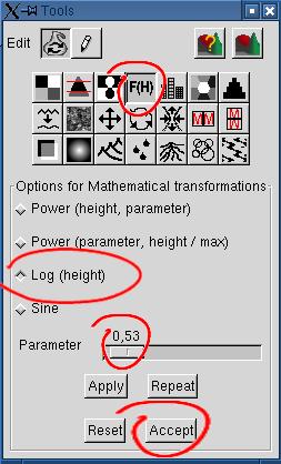 The proposed image, at the beginning of
this tutorial, shows a pond with a smooth shore. Raising slightly the
shore at the entrance of the cove obtained after step 6 would close the
cove. The log transformation allows this. It raises the lower parts of
the height field without raising the highest hills, while the deepest
parts remain black (think about the log curve to get the figure).
The proposed image, at the beginning of
this tutorial, shows a pond with a smooth shore. Raising slightly the
shore at the entrance of the cove obtained after step 6 would close the
cove. The log transformation allows this. It raises the lower parts of
the height field without raising the highest hills, while the deepest
parts remain black (think about the log curve to get the figure).The parameter is interpreted as a percentage. Using 0,5, over a maximum of 10, means that we merge 5% of the resulting log transformation with 95% of the original image. 0,5 or so is enough here, except if you want another effect. |
  |
 Back to the documentation index