Geomorph - How to draw cracks and fissures

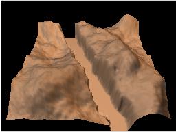
Geomorph version 0.22 provides an enhanced "fault pen", which can "separate" the fault in two walls, for creating cracks and fissures.

The fault walls separation is immediate. You see it in the 3D preview when you move the control scale.

Warnings...
Interactively separating two crack walls is a rather heavy process. With 512x512 height fields on an Athlon XP 2600+ (2,1 Ghz), it's comfortable, but if your increase the image size to 1024x1024, it slows down sensibly.
The separation is in "alpha" stage in version 0.22. Save your work frequently!

Topics A result


Faults, cracks and fissures, what are we speaking about exactly?


Faults, cracks and fissures can be approximated with Geomorph by using an irregular or a fractal line, generated from a random seed.

These are only geometrical imitations of geomorphological phenomenons, like most things that can be created with Geomorph. They are valuable as far as they "look like" reality to some extent!

Like seen in a previous tutorial, a fault is a difference of altitude separated by a fractal line.

crack is a fault dividing itself in two walls. The difference of altitude could be zero.

A fissure is a crack with a one-pixel or maybe two-pixel separation, with no difference of altitude.


Some principles

Overview

Cracks and fissures are created like faults, by drawing a control line with the mouse. The crack or the fissure is generated "under" the control line, following its slope. It can be adjusted precisely by moving the ends of the control line.

Dialog

Three components have been added to the pen fault dialog, for making cracks and fissures creation easier.


This button sets the difference in altitude to 0 instantly. In most cases, in a crack or a fissure, there are no difference between the height of the two walls.

This scale controls how wide is the separation. If a control line is currently active, moving this scale would widen the underlying crack instantly.

With this option, the currently active control line is automatically accepted when you click elsewhere in the height field to begin a new control line. The random seed is refreshed, so that the new fractal line is different. This is useful for drawing rapidly a network of fissures.

Direction of the separation


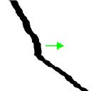
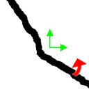
When the crack cuts a corner, the separation is done from the center to the outside, perpendicularly to the control line (red arrows, numbered from 1 to 4, in the following schemas). Then, the separation is done on both axis (green arrows).

When the crack cuts two parallel edges, the separation is done towards the bottom or towards the right (arrows 5 and 6). It is done on one axis (green arrows). If it were moving on two axis, there would be a black band on one of the edges.

When the separation is done on one axis and the slope of the control line is close to 45°, the crack line could be uneven. Then, it could look better if the control line is rotated sligthly so that the crack cuts a corner, like in situations 1 to 4.

Direction of the separation

When the slope of the line is close to 45°, it is better to avoid situations 5 and 6, because the width of the crack would look uneven.

You can get a nicer crack by rotating it so that it cuts a corner!.


How to create a network of fissures

Nature rarely shows us isolated fissures!

Rocks on which sea has removed plants and earth frequently exhibit a network of fissures.

Igneous rocks like granite crack in a less regular way than sedimentary rocks. The fractal line of the "fault pen" provides a reasonable imitation of these cracks.

In my country, the Canadian Shield meets the sea along the North Shore of the St Lawrence Gulf. Granite is very common. It has been polished by many glaciations and frequently shows a pinkish color.

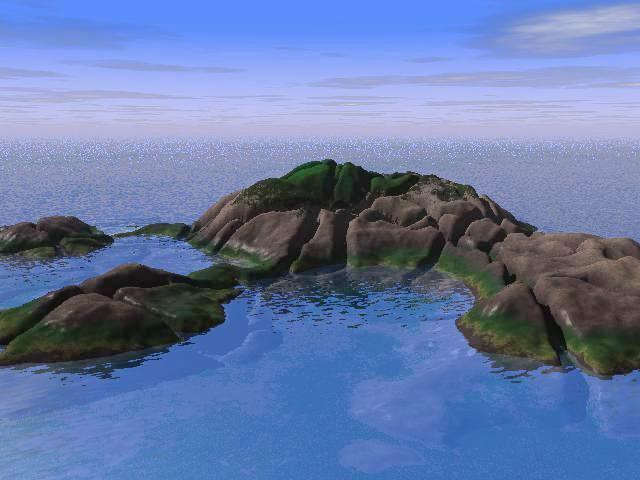
In this example, we will create a crackled reef of pink granite, rising up from the sea when the tide is low. The higher part is permanently out of the water and shows some low grassy plants.

This example uses the sea_and_rocks.pov scene and the geomorph_txtr.inc textures file provided with Geomorph 0.22 or later.

If these files are not in your working directory after upgrading Geomorph, copy them from  sea_and_rocks.pov and geomorph_txtr.inc.

1. Creating the height field

Create a new standard terrain.

We'll use here the default terrain of subdivision #2.


2. Decreasing the contrast for softening the terrain

We should decrease the contrast without keeping luminosity to get a low reef with a rather polished look.

Not keeping luminosity also allows to decrease the minimal height of the terrain to 0, which is the height of the oceanic floor.

We could also decrease the scale of the height field on the Y axis in the .pov scene definition. However, this effect couldn't be seen in the Geomorph preview.


3. Creating an Island (lowering the edges)

Use the "Shape Filter" option to lower the edges, so that no edge looks "cuit".

Advice You can also use the factal pen, in the "Dig a valley"mode, for erasing the edges.


4. Setting the camera position
 
Now you should select the Povray scene sea_and_rocks.pov for adjusting the terrain with the water. Click the Povray avec choix de scène icon at the top of the tools window.

The camera has been lowered and rotated so that the reef occupies the most part of the picture and so that the skyline divides the picture at approximately one third of its height, from the top.


AdviceCheck how the texture is applied. There could be a cycle if the top of the reef is too high, meaning that the dark rocky texture of the base would follow the grass at the very top. There are two ways to overcome this: decrease the contrast once more, without keeping the luminosity, or increase the scale of the texture in  sea_and_rocks.pov until the cycle disappears. The texture follows the line of "*" in the file:

object {hf  translate y*0 texture {shore_granite translate y*0 scale 0.25 } }

  Advice If the position of the sun in the rendered scene does not suit your taste, you can rotate the terrain with Geomorph instead of using the camera, with l'icône de rotation in the tools window. Moving the camera position does not change the sun position. If you rotate the terrain only in the preview (with the camera), the result could be a backlighted scene, acceptable in the preview but too dark in the rendered scene. The brightness of the rendered scene of this example has been increased with The Gimp for this reason...


5. Creating fissures repeatedly

Before beginning this step, save you height field!

Set the altitude difference to 0.

Choose a 1 pixel width.

Check if the "Auto Accept & Refresh" option is active (it is supposed to be the new default!). If not, you will draw the same fissure repeatedly.

Then, draw you mouse and shoot in all directions!

SuggestionModifying the smoothing parameter would slightly change the apparent width of the fissures. Use this break to save your work...


Three methods for creating a crack

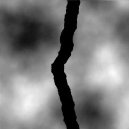
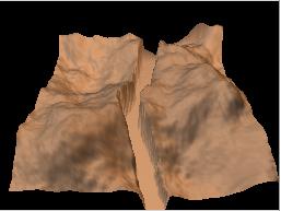
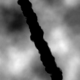
1. The "standard" way, by using the "separation" parameter of the fault pen.


2. By creating 2 identical faults, parallel but with inverted altitude difference.

A benefit of this technique is to allow the creation of a crack with walls which are not parallel.

However, this is not a true fault divided in two walls, but rather a sudden and narrow drop in altitude. The texture of the terrain surface is still visible at the bottom of the crack. You can remove it by decreasing the brigthness of the image, if you want.

Roughly, you can do it this way:
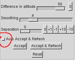
  • Unactivate the "Auto Accept & Refresh" option, for drawing two consecutive identical cracks.
  • Draw the first wall using a positive altitude difference.
  • Draw the second wall using the same altitude difference, but negative. Because Geomorph adjusts the altitude difference for avoiding overflow, the walls could be unequal. Correct the altitude approximately. In this example, the altitude for the first fault was 50, and it was corrected to -36 for the second one.
    • When drawing the second wall, if the fault is inverted comparatively to the first one, flip over the control line with the mouse.
These options were used for creating the first wall in the example at right:


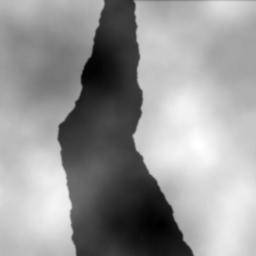
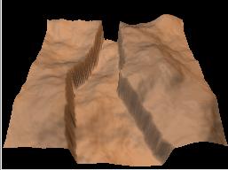
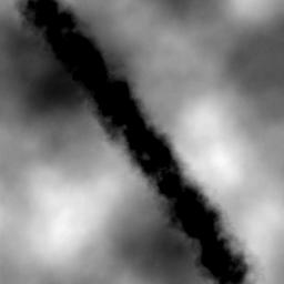
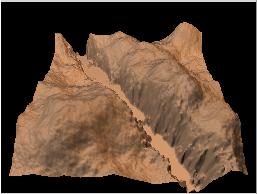
3. By digging the crack with a fractal pen - a vertical slope version.
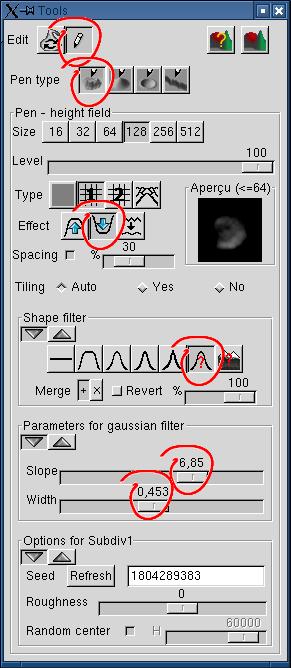
Here, we simulate the crack with a "valley" featuring steep walls. When the fractal pen is used instead of the continuous pen, the edges are kept irregular, even when the wall is vertical.

The pen level is set to 100%, because we want the highest altitude difference we can.

The "Dig a valley" option should be chosen.

The shape filter is used to adjust the slope of the pen edges. The "Gaussian Bell with parameters choice" has been chosen for better control.

SuggestionIf you prefer to adjust yourself the shape filter paremeters, as done this example, you can choose the "uniform" pen tip to get a better preview of the parameters effect. When you find the pen tip "hard" enough, revert to the fractal pen 1 or 2.


3b. By digging the crack with a fractal pen - an average slope version.
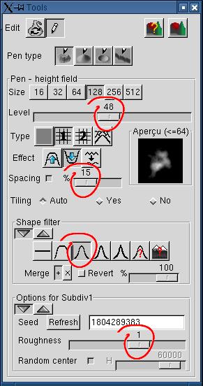
To get a lower and irregular slope, the pen level has been reduced by half. Also, a narrower shape filter has been selected.

The roughness had been increased from 0 to 1 to get more irregular walls.

The spacing has been reduced to 15%. otherwise the valley ground was too irregular.


Other hints
Top

Written in October, 2004

 Back to the Geomorph Home Page